It's a well known fact that the Weber Progressive carb has it's problems on the bus engine. It all stems from the long, unheated intake runners that take the fuel/air mixture from the carb, mounted over the centre of the engine, to the cylinder heads on either side. Remember grade nine science? If so, you'll remember the theory behind the latent heat of vaporization. This basically states that in order to turn something from a liquid to a gaseous state, it takes a lot of energy - for example, heating a pot of water on the stove to make steam.... Well, our carburetors turn liquid to vapour using a venturi principle, no heat. The heat energy, however, is still necessary, it's a scientific fact. Thus heat from the surrounding area is absorbed, making the intake runners cold to the touch, sometimes cold enough to form frost, even when the ambient temperature is above freezing. As these runners cool, they have the tendency to turn the air/fuel mixture back into a liquid which prevents the engine from running properly. In a nutshell, that's the science behind carb icing...
So, how do we solve the problem? Stock type 1 style engines used a heated intake manifold, which flows exhaust through itself to prevent the problem. They also used a warm-air intake system so the air that is being consumed is warmer than the ambient temperature. Carb icing is a real problem in airplanes. The solution there is carb heat, again a variation of warm-air intake.
I took a trip last April from Toronto to Myrtle Beach and back, by way of Everybus in NC. In the days before we left the weather turned unseasonably cold. I panicked and created the first warm-air induction system you see here. It worked great, letting the engine run perfectly for over 3000 miles, from below-freezing to 80 degree weather, including a blizzard in upstate NY and many miles of perfect icing conditions - damp, slightly above freezing. The biggest problem with the setup was that it was always on. It would draw warm air all the time, so I retrofitted a more permanent solution, which is also written up below.
Before the step-by-step, let's talk about warm air source... It's all good to get it to the carb, but where do you get it from? Well, my bus was originally a FI 2L. It was an early FI engine that had special rear tin that connected the air intake to a tube that ran across the top of the exhaust. Later buses did not have this provision. I don't run the stock exhaust, so this wasn't an option for me. After reading up on the subject, I learned that earlier type IV engines had a provision for a warm air intake from the #1 cylinder. It's a duct that connects to the lower passenger side tin where it scavenges warm air, and directs it through the firewall tin at the front (front is front) of the engine. I cut two 1.5" holes in my tin and copied this setup using ABS piping (2 90 degree fittings and a short section of pipe in between, secured with strapping)... This gives me a 1.5" fitting on the firewall for warm air!
On to the induction systems...
SYSTEM #1 - THE PROTOTYPE: The standard air filter is removed by unbolting it from the carb. The C-Clips are removed and discarded. Holes are drilled to allow for bolts to be installed and wingnuts. This allows the aircleaner to be opened and closed without access from underneath.
 The standard air filter is removed by unbolting it from the carb. The C-Clips are removed and discarded. Holes are drilled to allow for bolts to be installed and wingnuts. This allows the aircleaner to be opened and closed without access from underneath.
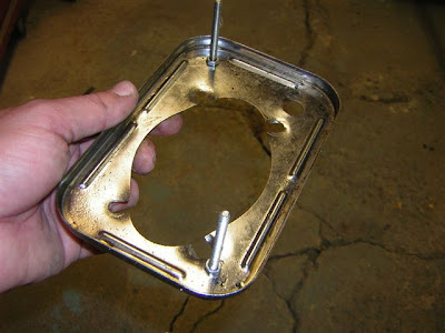 Showing the bolts in place.
 Here's a tin box I bought at Storage Solutions for $8.
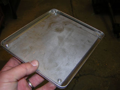 The lid had a plastic insert which I covered with a piece of scrap sheet metal that was bolted in place.
 I traced the lower air filter shape into the tin box and cut it out.
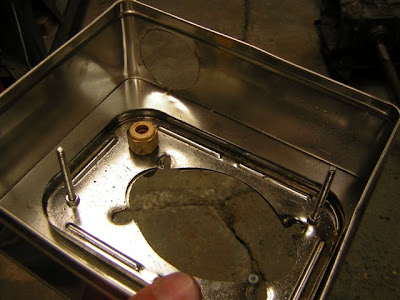 I then installed the bolts and crankcase ventilation fitting through the bottom of the tin and into the original aircleaner base.
 This shows the air filter reinstalled. Now you can see why the wingnuts were used to replace the C-Clips.
 This image shows the 1.5" hole I cut for the warm-air intake. It is not shown, but an ABS plumbing fitting was used here, a threaded one with a nut (fashioned from a female threaded ABS fitting, cut on the bandsaw) on either side of the tin, thus holding the fitting in place.
 This is the complete setup (intake pipe not shown). This unit works very well and was always warm to the touch while running, even in freezing conditions. I never experienced icing with this setup.
SYSTEM #2 - AIR INTAKE BOX RETROFIT
In the quest for a more permanent solution, I fashioned this out of a 1988 - 1992 Dodge Shadow (FI) Air Box. This was sourced from the wrecker and was the best I could find after looking at lots of cars. Unfortunately I couldn't find anything that used a progressive to start with, and the more traditional looking air cleaners (the round ones) were all too large....
 It's hard to make out, but this shows the completed system installed. Look to the right in the image and you can see the air intake with its flap currently open, allowing cool air into the system...
Heres a closeup of the crankcase ventilation hookup.
 Here's a view from the hatch looking down. As you can see this intake is well suited to the location of my incoming warm air and the layout of the engine bay.
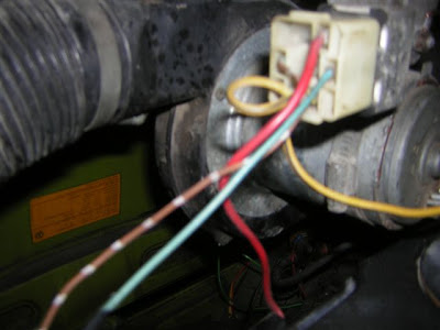 This shot shows that I loosened the clamp on the squirrel cage blower and moved it rearwards so it doesn't interfere with the intake.
 The air filter top removed.
 Looking into the system. You can see the temperature valve on the left. It allows vacuum (connected underneath) to close the flap in the intake to take in only warm air. When it gets too warm the vacuum is released and the flap opens.
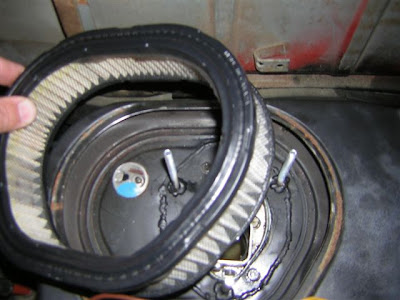 The new air filter, available anywhere. This one was $7 at Canadian Tire. I'm sure Walmart is even cheaper.
 Here you can see the warm air hose connected to the firewall on the right, and the new "T" and vacuum lines I installed to provide vacuum to the valve in the air box.
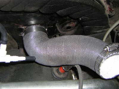 A close-up shot of my warm air connection.
 It's painted now, but this shows the fabrication I did to fit it to the progressive carb. The shape was pretty close and the surface pretty flat. I cut out the old lip with shears, then traced the shape of the old air filter on a piece of sheet metal, cut it to fit, and welded it in.
 I also welded some 1/4-20 bolts in place to hold the lid on with wingnuts.
 Here's a closeup of the cool air intake on the right and the crankcase breather hook-up on the left.
There are two big modifications to see here. Originally the warm-air intake was part of the plate on the left. It was only about 1" in diameter. I cut off that pipe with the bandsaw and cut a sheet metal plate to cover the area. The bracket you see was also welded to the sheet metal. It bolts onto the cross-bar on the intake runner for added support. The pipe on the right is the 1.5" ABS fitting originally used in SYSTEM #1. I cut a hole with a hole saw in the plastic casing here and installed it.
SUMMARY
Both systems have proven to work pretty well. The second one is new, I just made it on Thursday night, then went for a 300 mile tour on the weekend in temperatures just above freezing and lots of rain. There was no problem with this and the whole system and carb were warm to the touch.
The biggest (unexpected) plus of SYSTEM #2 is that it makes the engine quite a bit quieter. Tuning the intake air is actually a big portion of the noise reduction car engineers do. I was amazed how much quieter it runs at idle (before road noise takes over).
The biggest dissapointment of SYSTEM #2 was that by changing the location for the warm air intake on the air box I eliminated the positive switching of the valve between hot and cold air. It will now suck warm air until it gets warm enough to trigger the vacuum thermostat, then the flap will open and allow cold air into the system, but the hot air is not shut off by this process, so at best it's a mix.
For pure driveability SYSTEM #1 works great and is dirt cheap.
I hope this helps somebody...